Troubleshooting Your Wireless Bridge: Common Issues and Solutions
1. Why Isn’t My Wireless Bridge Getting Internet?
If your wireless bridge isn't connecting to the internet, it could be due to several factors. Check if your bridge is properly paired and configured to the correct access point or router.
2. Why Isn't My Wireless Bridge Pairing?
If your bridge isn't pairing, ensure that both the master and slave units are set to the same channel and that there’s no signal interference. Also, verify that both devices are powered on and connected to the network.
3. Why Isn’t My Wireless Bridge Working?
There could be several reasons why the bridge is not functioning properly. This includes incorrect configurations, network issues, or faulty hardware. Refer to the installation guide to double-check your settings.
4. How Can I Find My Wi-Fi Password?
The Wi-Fi password can typically be found in the settings of the wireless bridge’s user interface or in the product’s default manual. Make sure you have the correct credentials for access.
5. How Do I Make My Wireless Bridge Work as an Access Point?
To use your wireless bridge as an access point, set it to Auto Mode and follow the provided setup steps to configure it. This will enable it to broadcast a Wi-Fi signal and connect to your internet source.
6. How Can I Extend the Bridge’s Range with Internet Access?
If you need to extend the wireless bridge’s range, ensure that both the master and slave bridges are placed at optimal locations. You can also upgrade to higher-gain antennas or use multiple repeaters for further distance.
Quick Setup with Auto Mode: No Network Knowledge Required
If you're new to networking, setting up your wireless bridge in Auto Mode is the easiest option. Follow these steps to get your bridge working in just a few minutes:
Step 1: Unbox your wireless bridges and remove the back cover. Check the diagram below for guidance.
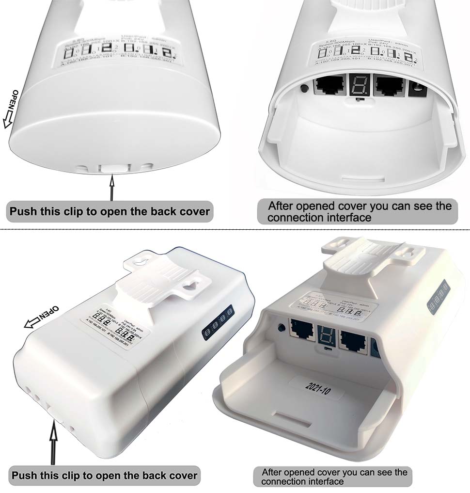
All the model CPE 335 | CPE 355 | CPE 365 | CPE450 | CPE220 | CPE 550 | CPE320 back cover is similar design, you can open the back cover by this step.
Step2: Move the mode switch to "A" position to set one bridge to master mode, and move another bridge's mode switch to "B" position to set to slave mode, please refer the below diagram:
CPE520 | CPE550 | CPE560 | CPE570 | CPE650 | CPE750 Interface:

CPE220 | CPE320 | CPE350 Interface:

Setting Up Wireless Bridge Models (CPE335, CPE355, CPE365, CPE450, CPE220, CPE550, CPE320)
All the models listed above have the same interface. Follow these simple steps to configure your wireless bridge:
Step 1: Set the Bridge to Master and Slave Mode
-
Move the mode switch to “A” to set the device to Master Mode (transmitting bridge).
-
Move the mode switch to “B” to set the device to Slave Mode (receiving bridge).
-
Ensure that one bridge is set to Master Mode and the other to Slave Mode.
Step 2: Internet Access Extension (Method 1)
-
Connect both bridges to their respective PoE power adapters.
-
Connect the Master Bridge to the internet source (router or modem).
-
Connect the Slave Bridge to a computer or another device that needs internet access.
Please refer to the diagram below for a visual guide on the connections.
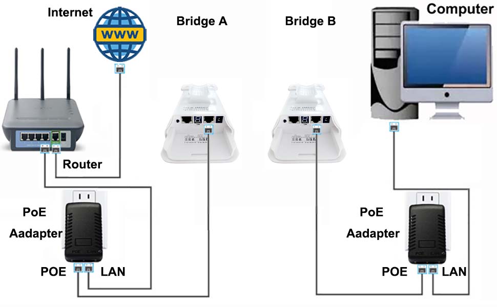

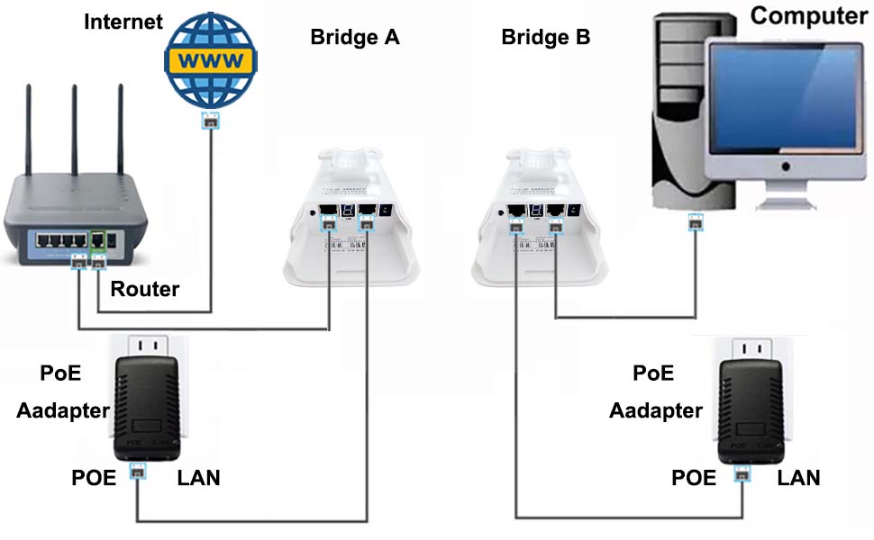
Bridge Setup for Internet Access
A. Master Bridge (Bridge A):
-
Set Bridge A to Master Mode by placing the mode switch in the "A" position.
-
Connect the LAN port of Bridge A to the POE port of the PoE adapter using a network cable.
-
Connect the LAN port of the PoE adapter to the LAN port of your router using a network cable.
-
Ensure your router is connected to the internet source (modem, gateway, etc.).
B. Slave Bridge (Bridge B):
-
Set Bridge B to Slave Mode by placing the mode switch in the "B" position.
-
Connect the LAN port of Bridge B to the POE port of the PoE adapter using a network cable.
-
Connect the LAN port of the PoE adapter to the LAN port of your computer using a network cable.
Once both connections are complete, refer to the diagram below for the network transmission path.
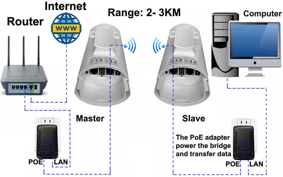
Transmission Path Example for CPE220 | CPE320 | CPE350 Models:
Please check the diagram for a detailed view of how the network will be transmitted.
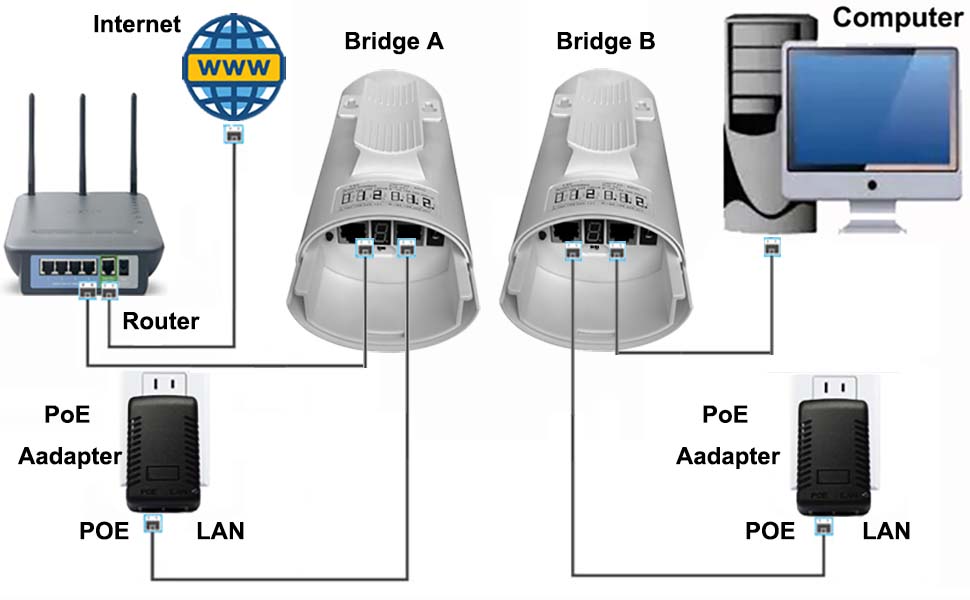
CPE520 | CPE550 | CPE560 | CPE570 | CPE650 | CPE750 Transmission Path 1:
Important Notes for Setting Up Wireless Bridges:
a. PoE Adapter Connections:
-
Ensure you connect the "POE" port of the PoE adapter to the bridge. The POE port provides power to the bridge and handles data transmission.
-
The "LAN" port of the PoE adapter is for data input or output to/from the bridge. Make sure to install the connections to the correct ports, as incorrect connections may result in no internet access.
b. Bridge Ports:
-
The bridge has LAN1 and LAN2 ports. You can choose either port for the connection, leaving the other port empty.
-
The DC 5V port on the bridge does not need to be connected to a power supply, as the PoE adapter powers the bridge via the network cable. Simply leave the DC 5V port empty.
c. Model-Specific Note for CPE220, CPE320, CPE335, CPE355, CPE365, CPE450, and CPE550:
-
Ensure that your router's LAN port supports 100Mbps speed, as these models only support 100Mbps transmission. Using a router with a higher speed may not work properly.
Bridge Setup for Internet Access (Method 2)
A. Master Bridge (Bridge A):
Set Bridge A to Master Mode by placing the mode switch in the "A" position.
Connect the "LAN" port of Bridge A to the "LAN" port of your router using a network cable.
Ensure that your router is connected to the internet source (modem, gateway, etc.).
B. Slave Bridge (Bridge B):
Set Bridge B to Slave Mode by placing the mode switch in the "B" position.
Connect the "LAN" port of Bridge B to the "LAN" port of the computer using a network cable.
Once both connections are complete, refer to the diagram below for the network transmission path.
Transmission Path Example for CPE220 | CPE320 | CPE350 Models:
Please check the diagram below for the detailed transmission path.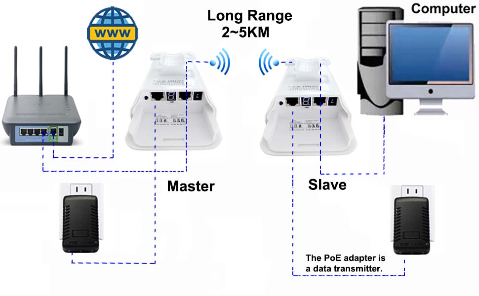
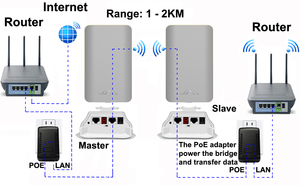
CPE520 | CPE550 | CPE560 | CPE570 | CPE650 | CPE750 Transmission Path 2:
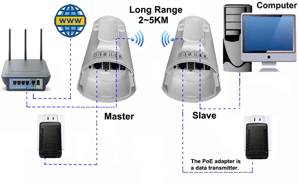
Note:
a. The bridge has two ports labeled "LAN1" and "LAN2". You can choose either port for data transfer and the other for power supply. Additionally, you can power the bridge via the DC 5V port, allowing you to connect it to a solar power system or solar panel. Please ensure that the voltage is 5V and the current is over 150mA for proper operation.
b. For models CPE220, CPE320, CPE335, CPE355, CPE365, CPE450, and CPE550, please ensure that your router's LAN port is set to the 100Mbps standard, as these models only support a 100Mbps transmission speed.
Post-Installation Instructions:
Once the installation is complete, the status LED light on both bridges will turn on, and the two bridges will automatically begin pairing within one minute. Please refer to the diagram below for further details on the connection process.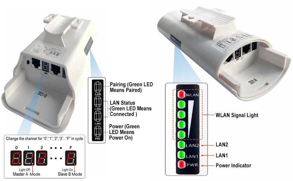
Bridge Status LED Indicators & Their Meanings
For Models: CPE335, CPE355, CPE365, CPE450, CPE550
-
Power Indicator:
-
When the bridge is powered on, the Power LED turns on, and the PoE adapter’s LED light also turns on.
-
-
LAN1 / LAN2:
-
When the data connection is successful, the green LED for LAN1 or LAN2 turns on. If the connection fails, the light will be off.
-
-
WLAN:
-
When the red WLAN LED turns on, it means the bridges are paired successfully.
-
The green signal LEDs (4 grid) indicate signal strength.
-
For Models: CPE220, CPE320
-
Power:
-
When the bridge powers on, the green LED will light up.
-
-
LAN1 / LAN2:
-
When the data connection is successful, the green LED will turn on.
-
-
Link:
-
When the green Link LED turns on, it indicates the bridges have successfully paired.
-
Digital Display & Its Meaning
-
Upon powering up, both bridges’ digital displays will flash a number for 30-60 seconds.
-
Once the bridges are successfully paired, the display will briefly show the letter "L" for 2 seconds, followed by a solid numeric display.
-
The corresponding LAN1 or LAN2 LED will also turn on, indicating successful pairing between the two devices.
Frequently Asked Questions
Q: Why is my wireless bridge not getting internet?
A:
-
Ensure that the PoE adapter is connected to the correct port.
-
Verify that the router LAN port is correctly connected.
-
If the above steps are correct, try switching to another LAN port on the bridge.
-
Make sure the two bridges are installed face to face. The antenna is directional, so misalignment can cause failure to pair.
Q: My bridge’s digital display shows “O”. What should I do?
A:
If you see “O” on the digital display, press the "RST" button for 10 seconds and release it. This will reset the bridge to factory settings, and it will attempt to pair again.
How to Change the Bridge’s Working Channel?
To avoid interference (especially with the 5.8GHz channel), you can switch the bridge to a different channel. Follow these steps:
-
Press the "RST" button to cycle through available channels:
-
Channels are represented by "0", "1", "2", ... up to "F".
-
-
Set both bridges to the same channel number and wait for 30-60 seconds for the devices to automatically pair.
-
Once paired successfully, the digital display will show the new channel number.
How to Find the WiFi Password
The SSID name and password are pre-programmed and vary depending on the bridge’s operating channel. The last two or three digits of the password correspond to the last digits of the SSID name.
For example:
-
If the SSID name is "CPE5G_5G161", the default password is "zllinkcpe123456161".
-
If the SSID name is "CPE5G_5G153", the password will be "zllinkcpe123456153".
Note:
-
Channels "A", "B", "C", "D", "E", and "F" do not output a WiFi hotspot.
-
For WiFi hotspot access, set the bridge’s channel to "0", "1", "2", ..., "9".
LED Indicator Number & SSID Password Chart
Please refer to the LED Indicator Number & SSID Password Chart to find your bridge’s SSID name and corresponding password based on the displayed number.
| LED Indicator Display Value | Channel ID | WiFi SSID | Password |
| 0 | 0 | CPE5G_5G0 | zllinkcpe1234560 |
| 1 | 165 | CPE5G_5G165 | zllinkcpe123456165 |
| 2 | 161 | CPE5G_5G161 | zllinkcpe123456161 |
| 3 | 157 | CPE5G_5G157 | zllinkcpe123456157 |
| 4 | 153 | CPE5G_5G153 | zllinkcpe123456153 |
| 5 | 149 | CPE5G_5G149 | zllinkcpe123456149 |
| 6 | 48 | CPE5G_5G48 | zllinkcpe12345648 |
| 7 | 44 | CPE5G_5G44 | zllinkcpe12345644 |
| 8 | 40 | CPE5G_5G40 | zllinkcpe12345640 |
| 9 | 36 | CPE5G_5G36 | zllinkcpe12345636 |
| a | 140 | ||
| b | 132 | ||
| c | 124 | ||
| d | 116 | ||
| e | 108 | ||
| f | 100 |
How to Make the Bridges Work as Access Points
Once both bridges are successfully paired, the master bridge will output a WiFi hotspot. This WiFi signal can extend up to 2 to 3 kilometers (in clear line-of-sight conditions, without obstructions), with a 60-degree coverage area.
The slave bridge can then connect to a router to share the WiFi signal in another building. The router can transmit the WiFi signal through 2 to 3 walls, making it ideal for extending coverage over large distances. Please refer to the diagram below for a visual representation of the setup.

Installing and Configuring the Wireless Bridges
-
Positioning the Bridges: Install both bridges facing each other, with the front sides aligned.
-
Master Bridge: Connect the master bridge to the router and internet source.
-
Slave Bridge: Connect the slave bridge to a router to forward the WiFi signal to devices such as computers, smartphones, and other devices.
-
WiFi Configuration: On the slave bridge's router, set the WiFi SSID name and password according to your preferences.

Setting Up the Wireless Bridges
-
Bridge Positioning: Place both wireless bridges facing each other, ensuring that the front sides are aligned for optimal signal transfer.
-
Master Bridge Setup: Connect the master bridge to the router and internet source to enable internet access.
-
Slave Bridge Setup: Connect the slave bridge to a router, which will extend the WiFi signal to other devices like computers, smartphones, and more.
-
WiFi Configuration: On the router connected to the slave bridge, configure the WiFi SSID and password to match your network requirements.

Auto Mode Setup Guide
The steps above are specifically for Auto Mode configuration. We highly recommend new users to start with this mode as it offers a simple and easy plug-and-play solution for extending your internet access or setting up video surveillance.
For a quick pairing guide, please refer to the Shortcut Guide. If you need more detailed instructions, check the Customize Mode Shortcut Guide or the Wireless Bridge User Manual.
If you have any further questions, feel free to reach out to us via email at johnwen0822@gmail.com or on Skype: johnwen0822.